db9 - How do I do the 6 pin RJ11 to RS232 female serial adapter wiring? - Electrical Engineering Stack Exchange
Confused about proper pinout with an RJ45 to DB9 adapter
Omron sysmac cable
How do I un-null modem a null modem cable?
What does the RS in RS 232 stand for?
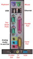
Does RS232 play any role in modern computers?
Videos

Note what Olin says - why do this? You may have a good reason but (as noted below) RJ11 is non standard for this purpose and you are inviting compatability problems.
There is NO RJ11 serial data standard. See examples below.
Advising whatyou want to connect to and why may make this task FAR easier.
Example at end of RJ11 serial data pinouts.
Brief comment below on finding unknown pinouts.
The answer to your question is given on the blackbox page that you referenced
- Pin your own modular adapter to connect your serial equipment.
The reason that they did not connect the RJ11 connector to the DB9 is that there IS no standard way available.
The reason that they left the wires uncommitted was so that you could connect them in the way that suits you.
If you do not know what the pinout you need is, who does? (Really). What are you connecting the RJ11 circuit to? What equipment? / model? / brand? Do they provide a datas sheet or connection diagram?
Worst case you may have some equipment that has a serial circuit on an RJ11 connector that you want to connect to. In this case, the very best method is to get the manufacturer's information. If this is not available then there are ways to proceed.
Finding the pinout of a 6 pin serial connector.
This is just an overview -m knowing the equipment brand and model or, failing that, type of equipment and intended use will help geatly.
6 wire connector.
Power off. Do any wires make low resistance connections with device chassis? Label as possible grounds.
Power on. Is any line at -5 to -12V wrt chassis ground. If only one this is probably TXD. Compare to diagrams below. Any clues?
If more than one low line one may be CTS or RTS or similar. With scope on check lines on turn. Depending on equipment TXD may have data burst. RTS may toggle or play around during startup.
etc.
More on this if needed.
Examples - these are useful mainly to show how thoroughly non standard the various arrangements are.
Dell RJ11 - one implementation

H2Ns page describing their RJ11 serial pinout and connections for interfacing to other equipment
H2NS's contribution to the fun.

Here's an interesting page from Unitronics they have a number of somewhat different "arrangements"
Here's a plug pinout from one of their several arrangements - it's notable for being different from but similar to the Dell arrangement above. TXD and RXD are the same and there's some other partial similarities.

CISCO RJ45 (NB not RJ11) (from)
1 n.c. <- 7 RTS bn
2 DTR <- 4 DTR bn/wh
3 TxD <- 3 TxD gn
4 GND 5 GND bl/wh
5 GND 5 GND bl
6 RxD -> 2 RxD gn/wh
7 DSR -> 6 DSR or
8 n.c. -> 8 CTS or/wh
The db9 connector will have the pin position numbers stamped on the front of the connector. They can be seen with a magnifier. The pins are inserted from the rear of the connector into the appropriate pin hole. Care should be taken to insert the correct pins as they can not be removed without a removal tool. These adapters work well, I have used them for RS232 many times before. As far as the pin out of the RJ11 you need to see what device it connects to and which pins correspond to the db9. The standard db9 pin out can be either a male or female connector and also DTE or DCE. You need to know what you are connecting to before you can determine the correct wiring.
I am attempting to control a device with RS232 commands.
The device has a control box that accepts RJ45 cable.
I am sending my commands via a Global Cache iTach WF2SL device which has a DB9 serial port.
I am attempting to connect the two devices using a Cat-6 T-568B cable, and a RJ45 to DB9 adapter.
The WF2SL pinout uses 2 - RX, 3 - TX, and 5 - Ground.
The control box expects what is in the image below:
 Screen-Pinout462×336 35.3 KB
The adapter has the following pinout definitions:
 Adapter Diagram831×771 47.9 KB
I’ve been trying to research this to determine the correct pinout but have become pretty much completely confused at this point.
I have ensured that the WF2SL is configured with the correct baud rate and additional settings.
I have tried quite a few different combinations of pinouts with no success.
Would anyone be able to dumb this down for me, and help me get the right pinout on the adapter, using the Cat-6 cable I have, to work with what the device is expecting?
Thanks in advance.
2 to 3, 3 to 2 and 5 to 5.