Series circuit
simulate this circuit – Schematic created using CircuitLab
Figure 1. Five LEDs in series.
LEDs aren't linear (current is not proportional to voltage as in a resistor) and small increases in voltage can cause a large increase in current to the point of destruction. A series resistor will limit the current to a safe value provided voltage doesn't deviate too much.
Since you require 2 V per LED at 10 mA that means we need to drop another 2 V in the series resistor. From Ohm's Law, \$ V = IR \$, we can calculate \$ R = \frac {V}{I} = \frac {2}{0.01} = 200~\Omega \$. 220 Ω is the next highest standard value.
Parallel connection
simulate this circuit
Figure 2. Parallel circuit.
This time each LED requires its own resistor which needs to drop 10 V across it. Using Ohm's Law again we get \$ R = \frac {V}{I} = \frac {10}{0.01} = 1000~\Omega = 1~k\Omega \$.
Use a 220 ohm resistor, assuming you connect the LEDs in series. If they are parallel, use a 1.2Kohm for each. There are several good websites you can use to calculate this, here is the first Yahoo! link: ledcalc.com
I have been looking at adding an LED light to the top of my rack and it seems dumb to add a giant AC-DC transformer and second plug to the wall just for the light when I have a DC 12v rail here in the eurorack power supply.
Is this a bad idea? How to make this happen?
I figure all it would need is a power header with a line to the switch and back to ground but I am new to this game and not sure what I am missing.
The easiest way is to use dual-throw switch (also known as DPDT, SPDT, or ON-ON) with a independent light input.
Here is one example: http://www.mouser.com/ProductDetail/NKK-Switches/MLW3012-12-RC-1A/
In this case the common is 2, switch toggles between 1 and 3, and lamp is on separate L+ and L- pins. So you will want to connect common to 12V supply, then pin 1 will go to your lights, while pin 3 will go switch's light (L+). L- goes to ground.
If you cannot find ON-ON switches in the style you like, it will be possible to use regular single pole (SPST / ON-OFF) switch by "shorting" back light when the switch is on. However, this method will waste power, so I only recommend it if you cannot find ON-ON switches you like. Let me know if you are interested in that.
What you want to do is very easy if you use a SPDT rocker switch. Many will be available that way.
I was going to post a schematic, but I get a message that imgur rejected the image for some reason.
Connect the center of the switch to the 12 V power. Then either side will be powered, depending on how the switch is thrown. The one that is powered when the switch is in the OFF position has a LED and resistor in series. The other is the switched power to run your load.
Schematic added
Imgur seems to be up again, so here is the schematic I tried to post yesterday:
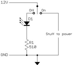
Again, one of the two branches will be powered at any one time, but not both. Rocker switches are easy to find in SPDT configurations. In fact, that's probably the most common.